3D Designer
Language Basics
Here too the basics are, well, basic:
cube (5);
prints a cube with sides measuring 5 units. In my case, that translates to millimeters when I send it to my printer. The cube's lower left-hand corner on its front face is at the [0, 0, 0] position (Figure 1 again), so the cube is drawn to the right, up, and back from the viewer's initial point of view.
Although this is the default, you can add another parameter to the cube as follows:
cube (5, center = true);
to make the center of the cube coincide with [0, 0, 0], and then the cube is drawn around its central reference point.
You can also create in a similar way spheres, cylinders, and polyhedrons, the latter being customized 3D shapes.
To make the object appear in the preview pane, press the render button in the toolbar at the top of the script editor pane (second from right), or in the toolbar under the preview pane (second from left). You can also hit the F6 key.
You can move things around with the translate () function and rotate them with the rotate() function. To make this work, you embed the shape you want to modify within the function that modifies it. Listing 1 shows several ways you can do that.
- In Method 1, you simply put all the commands on one line, with the inner-most nested element last and moving outwards as you move backwards to the beginning of the line.
- Method 2 is a bit clearer, as it uses a notation similar to JavaScript or C/C++, where you user braces (
{}) to enclose nested blocks of code. As we are on the topic of C/C++, notice how the OpenSCAD's language uses C/C++ style comments, with//to indicate a line comment and/* ... */for multiple lines of comments. - Method 3 is similar to Python, as you use indentation at the beginning of the line to indicate which block of code is nested within which container.
In our example, you may be tempted to think that there is some sort of invisible 3D cursor at work. When you write
translate ([x, y, z])
it moves said cursor to coordinate x, y, and z. Then, when the renderer executes
rotate ([a, b, c])
it rotates the cursor in 3D space and then draws the cube.
However, that is not what happens. In fact, the renderer executes commands inner-most first and moves out from there. Think of it like this: The renderer first locates the object it has to actually draw. The operation nearest to the object gets applied first, then the next to nearest, and so on, until all operations have modified the object. In the example above, that would be the rotation is applied first and then the translation.
This is important, because the order in which modifications are applied to a body matter. In fact,
translate ([5, 5, 5]) rotate([45, 45, 45]) cube (5);
will give you a quite different result to:
rotate([45, 45, 45]) translate ([5, 5, 5]) cube (5);
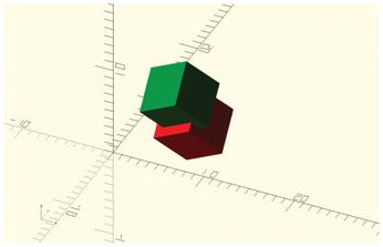
Figure 2 shows both. The green cube shows what happens when you rotate first and then translate, and the red cube shows what happens when you translate and then rotate. They are in different positions because with the green cube, you rotate the cube while it is still located at [0, 0, 0] and then move it to where you want it to be (which is what you probably wanted to do all along). With the red cube, you move the object and then rotate, but the rotation takes the original point as its reference, so it moves the cube on a 45 degree arc measuring 5, with its origin at [0, 0, 0].
Adding and Subtracting
There are several ways of creating complex parts in OpenSCAD. One of them is by adding, intersecting, and subtracting one object from another. Listing 2 shows a cube that has had a sphere subtracted from it (Figure 3).
Listing 2
Cube Minus Sphere
difference () {
  cube (10, center = true);
  sphere (6.5, center = true);
}
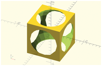
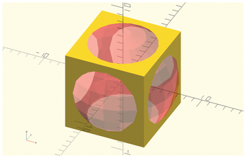
The way this works is that the second object (sphere ()) is subtracted from the first (cube ()). Notice that, due to OpenSCAD's scripting nature, objects never "go away" when you operate on them. In fact, you can still show subtracted pieces by typing a # in front of them and then hitting Preview (the F5 key). The "ghost" objects will show up as a translucent piece in the display pane (Figure 4).
Another way of showing all the bodies that make up a piece is by marking the checkbox at View | Thrown together in the menu.
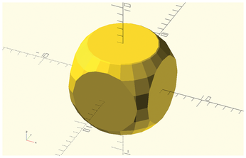
The other two Boolean operations available are intersection (), in which you are left with an object that shares the space common to the two original objects (Figure 5), and union (), which just melds both objects together.
Special Variables
You will notice that the sphere in the example above is looking a bit chunky. There are several inbuilt variables that can help with that. $fn, for example, sets the number of subdivisions in a curve. Use it like this
sphere (6.5, $fn=25);
to create a sphere with 25 subdivisions on each of its parallels.
In Figure 6, you can see what three spheres look like with, from left to right, the $fn variable set to 5, 25, and 50. The "sphere" (to call it something) on the left has north and south poles and an equator made from pentagons. Meanwhile, the sphere with a $fn of 50 looks much more sphere-like.
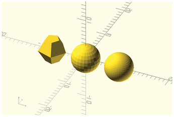
You may be tempted to make $fn equal to 500 or 1000 to get a perfectly smooth sphere. Don't do that. Anything over 100 will eat up cycles from your CPU like candy, probably crashing your system. Besides, you are producing objects to print on a 3D printer. You'd need a crazily precise printer to be able to distinguish between a sphere with a $fn of 50 and another with a $fn of 500.
« Previous 1 2 3 Next »
Buy this article as PDF
(incl. VAT)
Buy Linux Magazine
Subscribe to our Linux Newsletters
Find Linux and Open Source Jobs
Subscribe to our ADMIN Newsletters
Support Our Work
Linux Magazine content is made possible with support from readers like you. Please consider contributing when you’ve found an article to be beneficial.

News
-
TUXEDO Computers Unveils Linux Laptop Featuring AMD Ryzen CPU
This latest release is the first laptop to include the new CPU from Ryzen and Linux preinstalled.
-
XZ Gets the All-Clear
The back door xz vulnerability has been officially reverted for Fedora 40 and versions 38 and 39 were never affected.
-
Canonical Collaborates with Qualcomm on New Venture
This new joint effort is geared toward bringing Ubuntu and Ubuntu Core to Qualcomm-powered devices.
-
Kodi 21.0 Open-Source Entertainment Hub Released
After a year of development, the award-winning Kodi cross-platform, media center software is now available with many new additions and improvements.
-
Linux Usage Increases in Two Key Areas
If market share is your thing, you'll be happy to know that Linux is on the rise in two areas that, if they keep climbing, could have serious meaning for Linux's future.
-
Vulnerability Discovered in xz Libraries
An urgent alert for Fedora 40 has been posted and users should pay attention.
-
Canonical Bumps LTS Support to 12 years
If you're worried that your Ubuntu LTS release won't be supported long enough to last, Canonical has a surprise for you in the form of 12 years of security coverage.
-
Fedora 40 Beta Released Soon
With the official release of Fedora 40 coming in April, it's almost time to download the beta and see what's new.
-
New Pentesting Distribution to Compete with Kali Linux
SnoopGod is now available for your testing needs
-
Juno Computers Launches Another Linux Laptop
If you're looking for a powerhouse laptop that runs Ubuntu, the Juno Computers Neptune 17 v6 should be on your radar.

