Create vector graphics with LibreOffice Draw
New Shapes
If the existing shapes do not satisfy your needs, you can generate new shapes using the shape operations Merge, Subtract, and Intersect. For example, to draw a convex-concave lens (Figure 4), you start by drawing a large circle and a small circle and pushing the two on top of one another. Then center the two circles by selecting Alignment | Centered in the context menu.
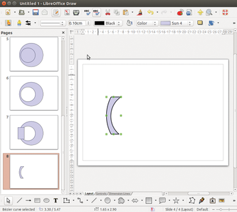
Next, subtract the small circle from the large circle: To do this, press and hold down the Shift key and click on both objects. Right-click to open the context menu and below Shapes select Subtract. The big circle now has a large hole in the center. Next, superimpose a rectangle on the front part of the hole; select both objects again and then Alignment | Center. Finally, call Shapes | Intersect in the context menu. If you lost the border in this operation, you can now restore it.
Component Library
Composing elementary objects that you then use to create complex objects for use over and over again in different pieces of work is particularly useful. In this section, I take a look at how this works based on a simple library of electrical symbols (Figure 5).
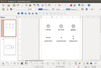
For example, the voltage source consists of two centered, filled circle objects that you superimpose using Alignment | Centered. To create a single object, right-click and select Group from the context menu. The objects grouped in this way can then be copied to new electrical circuits. Do the same with the other objects. Finally, you need to label the components.
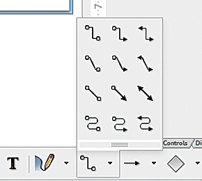
To connect the individual components, use a Connector object from the drawing tools at the bottom. The type of line drawn is set by the connector type chosen (Figure 6). After enabling the tool, click and hold the mouse pointer on a "glue point" that appears on the first object you select. This docks the connector to the object. Still holding down the mouse button, drag the pointer to a glue point on the next object. Dock the line at the desired location by releasing the mouse button.
If you did not initially align the connected objects precisely, then you will see some unintended steps in the connecting line. As soon as you move the connected objects on the workspace, the line routing is automatically corrected. Using the Glue Points tool (symbolized by a glue tube in the drawing tools) is also recommended when you are working with the connector tool. This lets you define the connection points of a PNP transistor or another complex component, for example, and then attach connecting lines in the right places.
Good Teamwork
LibreOffice's special advantage is that it is a suite of program modules that you can expect to work together perfectly. The version used in our lab, LibreOffice 4.2.7.2, worked well in this respect, whereas earlier versions occasionally experienced formatting problems.
In the example here, the task is to insert a simple circuit diagram into a LibreOffice text file. To do this, you again select all the objects in the drawing and copy them using the Edit | Copy menu item or Ctrl+C. Next, use the mouse to change to the open text document and move the items that you want to insert into the circuit diagram to the appropriate location; finally, add the diagram by selecting Edit | Paste Special or pressing Ctrl+Shift+V.
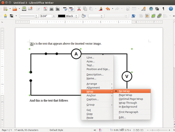
The recommended object type to select in this step is GDI metafile, because it will cause the fewest problems when inserting the image. The To Paragraph option in the Change Anchor drop-down on the menubar and Wrap | No Wrap from the context menu are recommended for positioning exported objects in the text, especially if you are exporting to third-party formats such as PDF and HTML (Figure 7).
« Previous 1 2 3 Next »
Buy this article as PDF
(incl. VAT)
Buy Linux Magazine
US / Canada
UK / Australia