Simulate digital circuits with Logisim
Multiplex Connection
In multiplex cinemas, people walk in at a common entrance and take a seat in the desired theater. An n-bit multiplexer works similarly. However, encoders, which simulate the end of a movie night, wherein visitors come out of the individual cinemas and leave the building from a common exit, need a closer look.
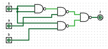
The design of a parallel 1-bit multiplexer (Figure 8) begins in the Combinational Analysis window. To start, create the appropriate truth table and then click Build Circuit. In the window that opens, select the NAND gate and assign a name to the circuit. A NAND operator corresponds to an inverted AND operator. NAND gates are considered universal, because any logical function can be implemented by this type alone.
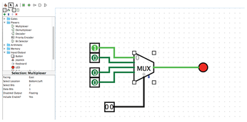
To create a multiplexer manually, open the Plexers library and drag a Multiplexer onto the canvas. For a 2-bit multiplexer, you need two data lines and one control bit, which you set in the Select Bits and Data Bits drop-downs, respectively, in the attribute table (Figure 9). This combination gives you four inputs (00, 01, 10, 11) numbered 0 through 3, another input for the selector (control) pin, and one output. After connecting pins to the inputs of the multiplexer, set the control signal – found on the bottom side of the multiplexer – to 2 bits in the attribute window, and then add an LED for the output, which is found under Input/Output | LED.
Divide and Conquer
When programming, you reuse code by creating functions (subroutines, methods), and you do the same thing in Logisim by creating subcircuits.
To create a timed circuit, you can integrate the aptitude test, which in this case represents the logic, between two D flip-flops. To start, create a new circuit by calling up the context menu of the project folder with a right-click, choose Add Circuit, and give it a name. Drag two flip-flops to the canvas.
To insert the example subcircuit between the two D flip-flops, click once on the name of the subcircuit in the tree structure on the left. The mouse pointer changes to a block that represents the subcircuit, which you now add to the canvas and connect to the flip-flops (Figure 10).
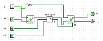
The D flip-flop has only one output, which also needs to go to an input on the subcircuit, so you need to add two more input pins to the subcircuit. The subcircuit has two outputs, one of which you connect to the input of the second D flip-flop. The other output goes to the reset input (~R) of the second D flip-flop.
Testing
The most beautiful circuit is of little use if it doesn't work, so you should test your circuit before using it. To test logical circuits such as this aptitude test, choose the Poke (pointing finger) tool in the menubar. By clicking an input pin several times, you can change its value and observe the behavior of the outputs. Logisim color highlights active lines (i.e., those through which data bits are currently flowing) during the simulation.
Logisim has a special feature for time-controlled circuits: The Simulate | Ticks Enabled menu item automatically starts ticking the clock, so you only have to change the data inputs to observe the circuit's behavior.
Logisim also offers an export function that creates a drawing of the circuit under File | Export Image. In the resulting window, you select the desired image format and scaling.
« Previous 1 2 3 Next »
Buy this article as PDF
(incl. VAT)
Buy Linux Magazine
US / Canada
UK / Australia