Controlling a cheap smart plug from Linux
Flashing the Firmware
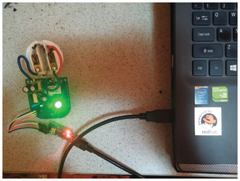
Connect the GND cable coming from the controller to the GND pin on the board, the 5V cable to VCC, the RDX to TDX, and the TDX to RDX.
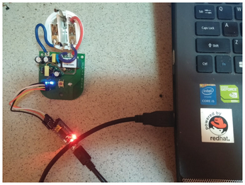
Now power up your Linux laptop or PC and connect the USB cable to it. The FTDI controller's LED should glow red, and the LED on the smart plug should glow green (Figure 5). The next step is to put the Sonoff S20 into programming mode. Press the smart plug's power button (it only has one button) and, while holding it down, take out the USB cable from the laptop. While still holding down the button, wait for three seconds, insert the USB cable back into the USB port, and release the power button after another two seconds have passed. If all went well, the smart plug's LED light should glow blue (Figure 6). If not, repeat the steps until it does.
If you do an lsusb in a console emulator, the Linux kernel should detect the FTDI controller (Figure 7).
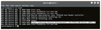
To check what USB port the smart plug is connected to use
$ dmesg | grep tty
The Sonoff S20 comes with an ESP8266 chip [5]. The ESP8266 includes WiFi support and a full TCP/IP stack to receive commands for controlling the device. To get control over the smart plug, I'll replace the firmware on the ESP8266 with the ESPEasy open source firmware [6], which is available for free download. You'll need to download the esptool.py Python script to flash a new firmware image on the Sonoff S20. Be sure to make the script executable:
$ wget -c https://raw.githubusercontent.com/letscontrolit/ESPEasy/mega/test/esptool.py
$ chmod +x esptool.py
You also need to install Python and the Pip package manager for Python packages. If you use a Debian-based distribution, you can install Python and Pip with:
$ sudo apt install python pip
Once Python and Pip are in place, you need to install pyserial using Pip:
$ pip install pyserial
Download the 2.0.0-dev12 version of the ESPEasy firmware with:
$ wget -c https://github.com/letscontrolit/ESPEasy/releases/download/v2.0.0-dev12/ESPEasy_v2.0.0-dev12.zip
Unpack the firmware from the ZIP file, and you should get a firmware file named ESPEasy_v2.0.0-dev12_normal_1024.bin. Assuming the USB port of the FTDI controller is connected to /dev/ttyUSB0 and that you remained in the same directory as the firmware file, you can now reflash the smart plug with the following command (Figure 8):
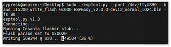
$ sudo ./esptool.py --port /dev/ttyUSB0 --baud 115200 write_flash 0x000 ESPEasy_v2.0.0-dev12_normal_1024.bin -fs 8m
Make sure you use 115200 as a baud rate. The flashing will be done in about a minute, and after that, you can disconnect the USB cable and reconnect it so that the Sonoff S20 will exit programming mode.
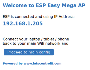
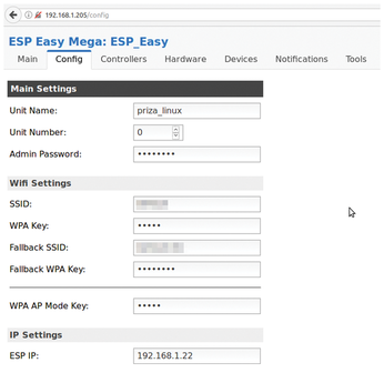
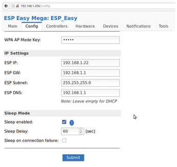
The new firmware has been flashed. If you check your surrounding WiFi networks, you will find one called ESP_Easy_0. This network's WiFi password is configesp; you will have to connect to it with the help of a web browser to be able to configure the smart plug. The smart plug's IP address has changed to 192.168.1.205, so be sure to navigate to this IP address. A web page with a message should greet you (Figure 9). Now you have to disconnect from this WiFi network, connect to your own WiFi network, and click the Proceed to main config button. This button will allow you to pick your WiFi network and enter your WiFi network password. You can change your smart plug's IP configuration to match the netmask of your own local area network (Figure 10) or use DHCP to give the Sonoff S20 a dynamic IP address (Figure 11).
Configuration
The new firmware you flashed has Telnet features, can handle both 2.4 and 5GHz WiFi networks simultaneously, has a logging system, has an information panel with statistics, and even has a place to set custom commands to be executed by the smart plug's power button. It can send you email notifications, update the current firmware through a web interface so you won't need to use an FTDI controller again, and – most importantly – it has support for the MQTT IoT protocol, which you will use to remotely control the Sonoff S20 through Linux.
You'll need to set up openHAB and an openHAB client like Mosquitto. Mosquitto is an open source MQTT broker maintained by the Eclipse foundation. To install Mosquitto on your Linux computer, use:
$ sudo apt install mosquitto mosquitto-clients
You can now set up the configuration for the power button with
# mosquitto_sub -h my.mqtt.server -t "#" -v
/sonoff-s20/Relay/State 1
and
# mosquitto_sub -h my.mqtt.server -t "#" -v
/sonoff-s20/Relay/State 0
Using Linux and Mosquito, you can start and stop the smart plug from the command line with:
# mosquitto_pub -h 192.168.1.22 -t "/sonoff-s20/gpio/12" -m "1"
and
# mosquitto_pub -h 192.168.1.22 -t "/sonoff-s20/gpio/12" -m "0"
where 0 stands for Power Off and 1 for Power On, assuming the IP address of the smart plug is 192.168.1.22.
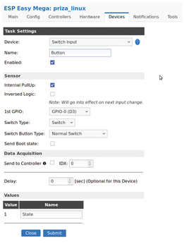
After you configure the smart plug using the built-in web server, click on the Devices tab. Under Task Settings, choose Switch input as the device and name it Button (Figure 12). Check the box next to the Enabled field, check the one next to Internal PullUp, and underneath that select GPIO-0 (D3) as the 1st GPIO. Choose Switch Type as Switch and Switch Button Type and Normal Switch; then, under the first value name, enter State. Click the Submit button to save these settings. Now do the exact same thing for GPIO-12 (D6), but this time also check the Send to Controller checkbox and name the new device Relay instead of Button (Figure 13).

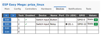
Under the Devices tab, you now should have two devices: one named Button with a GPIO value of GPIO-0 and another named Switch with a GPIO value of GPIO-12 (Figure 14).
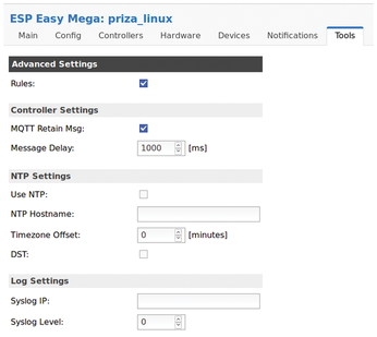
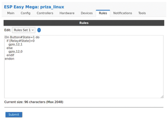
Now you need to create a ruleset for the power button. Click on the Tools tab and check the checkbox next to Rules (Figure 15). A new menu will appear, in which you can insert your own rules that define the behavior of the power button. Enter the contents of Listing 1 into this editable field (Figure 16).
Listing 1
PowerButton Configuration
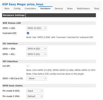
Under the Notifications tab, you can configure your email address so that whenever the smart plug does something, you will be notified through an email. Finally, under the Hardware tab, you need to make the following changes: Set GPIO-LED to GPIO-13 (D7) and check the Inverse LED checkbox. Under I2C Interface set GPIO-SDA to GPIO-4 (D2) and GPIO-SCL to GPIO-5 (D1) (Figure 17).
To actually control the Sonoff S20, create a new ruleset with the code in Listing 2.
Listing 2
Start and Stop Functions
Control the Smart Plug from a Web Browser
Save the new ruleset, and from this moment on, you can open up a browser tab and launch
http://192.168.1.22/control?cmd=event,start
to start the smart plug and
http://192.168.1.22/control?cmd=event,stop
to power it off remotely. Any device connected to it will thus power on or power off along with the smart plug. To start the plug and leave it powering whatever it has been connected to for exactly seven minutes, you can use the ruleset in Listing 3. Seven minutes is plenty of time for your coffee machine to get ready, make coffee, and power off when it's done.
Listing 3
Making Coffee for Seven Minutes
« Previous 1 2 3 Next »
Buy this article as PDF
(incl. VAT)
Buy Linux Magazine
US / Canada
UK / Australia