Real-World Raspberry Pi
Exploring the Raspberry Pi through real-world projects
ByThe single-circuit-board Raspberry Pi computer, only as big as a credit card, makes it easy to gain experience with embedded Linux systems. We’ll show you some hands-on examples of how to use the Raspberry Pi in an everyday environment.
British engineer Eben Upton and a team of like-minded hardware hackers started the Raspberry Pi project as a means for providing affordable computer technology for interested young people. The objective was to develop and market a single-board, credit-card-sized computer compatible with the often-narrow budget of the target group (see the “History” box).

If you find yourself reminded of the first home computers, you are not completely off-target: The explicit goal of the founders was to recolonize basements, garages, and classrooms with the spirit of the generation that had grown up with the Atari 400/800, ZX80/81, or VC20/C64.
Almost one year after the Raspberry Pi appeared, it is appropriate to look back over what has happened between the first series of approximately 10,000 pieces and the present status approaching 1,000,000 pieces delivered: How successful has the project been? What capabilities does the hardware offer? What is possible, and what is not (yet) possible? This article explores the Raspberry Pi system through three real-world projects:
- a multimedia, video playback system,
- a wireless access point, and
- an embedded temperature controller unit.
The first project is an example of the Raspberry Pi system serving as a replacement for a standard desktop computer. The latter two examples showcase the Raspberry Pi as an embedded system, which will require a little programming knowledge but, also, will give you a glimpse into the versatility of this mighty little mini-computer. Perhaps all three examples will help you imagine other do-it-yourself projects you could create with your own Raspberry Pi.
Shopping List
Originally, the designers had planned an A and B model, which were to differ mainly in the number of USB ports (one or two), the availability of an Ethernet port, and, of course, price (US$ 25/35). At this time, only model B is available. See Table 1 for a summary of Raspberry Pi components.

To get the Raspberry Pi (or RasPi for short) up and running, you need to make a list of the basic components. The Internet has more for tips on advanced operations. Three global distributors offer the board, according to the Raspberry Pi FAQs page. Although delivery times of a few months were not unusual in the spring of 2012, you now generally only have to wait a few weeks.
Besides the board itself, you will need the following components:
- A USB power supply with no less than 700mA. If you want to power additional hardware through USB, you should plan at least 1 amp.
- An SD(HC) card with at least 2GB capacity; however, 4GB would be better. Depending on what you intend to do, that still might not be enough. Because the system is also housed on the SD card, it is advisable to choose a card with a high read and write speed.
- For wireless access, a WLAN adapter in the form of a USB stick would be practical. But in practice, a USB WLAN adapter is often a significant factor in power consumption. If you are considering using a USB adapter, be sure the driver is supported and choose a slim design that does not block the second USB port.
- In view of the low number of USB ports, a wireless keyboard and mouse would be a worthwhile investment that would also save unnecessary load on the limited resources of the USB power adapter.
In addition to these items, you will also need various cables, such as HDMI or Ethernet, depending on the planned use. As far as the HDMI cable is concerned, the shorter the better. You do have the option of increasing the output of the driver, but that also increases power usage. If you plan on listening to music or watching videos, you will also need headphones or speakers.
The third project (an embedded temperature controller) uses an expansion board that requires some additional hardware.
Getting Started
A Debian-based Linux distribution known as Raspbian is tailored for duty as an on-board operating system for Raspberry Pi. The Raspberry Pi foundation recommends the Raspbian “Wheezy” release, which is used in this workshop.
Start by downloading the Raspbian “Wheezy” image file, which is a complete system image consisting of a 60MB boot partition and a root filesystem of around 2GB. Unpack the file and move it to an SD card with the following command:
$ sudo dd bs=1M if=2012-08-16-wheezy-raspbian.img of=SD_card_device_filename
Now, plug the SD card, keyboard, mouse, and monitor into the Raspberry Pi system and boot by connecting the USB power supply. The configuration menu then appears, and if you are not using a standard English keyboard, it would be best first to change the settings under the menu items configure-keyboard and change_locale to the keyboard and language of your choice; otherwise, you will encounter problems as soon as the login is required. The default username is pi; the password is raspberry.
Other useful menu items include change_timezone, to set the correct time zone; ssh to enable safe access to the terminal via network; and expand_rootfs, to change the size of the root filesystem from 2GB to the actual size of the SD card. Finally, you should update the system in the typical Debian manner:
$ sudo apt-get update
$ sudo apt-get upgrade
You can start the configuration tool anytime using sudo raspi-config.
Project 1: Playing Video
Entering startx will take you to the LXDE graphical desktop, which is optimized for lean systems. Playing an HD video is certainly the ultimate test for the hardware. The usual video players, however, are of no help because the GPU on the board is optimized for decoding audio and video data. Accordingly, you need a player that uses Broadcom’s own program library (found under /opt/vc). Currently, the only one that does that is the pre-installed command-line program omxplayer.
If possible, simply mount the directory containing the files over your network. NFS offers faster access to your video collection, but SSHFS is less complicated. The appropriate packages are installed, as shown in Listing 1. You then start playback with the omxplayer <File> command.
Listing 1: Setting Up a Video Player
$ sudo apt-get sshfs
$ sudo adduser pi fuse
$ mkdir myVideos
$ sshfs username@host_name:/directory_name myVideos
After a short hiccup in picture and sound, the software played the test HD video in 720p format with a 5.1 Dolby Digital audio track – of course, mixed down to two channels – without any jerkiness. And that’s all as far as the spartan Omxplayer is concerned. The program does demonstrate impressive capabilities for decoding audio and video, but nothing more. There are also two more drawbacks: The video library mentioned above is not open source software, and you must purchase licenses for the MPEG-2 and VC-1 formats.
Energy use, on the other hand, is surprisingly low: The average load while rendering the HD video was only 3.8 watts, despite the demanding task of transmitting via the network. The programs Omxplayer, SSH, and SSHFS create the biggest load for the CPU and memory, whereas the player claims the larger share for itself. However, if you want to play HD video with 1080i or 1080p, it is worth connecting the network drive via NFS.
Embedded Systems
The second and third projects employ the Raspberry Pi as an embedded system on a network – without a keyboard, mouse, or monitor, but with LAN/WLAN access. On such a system, you can read out the messages on startup with a terminal on the serial port. If an error occurs in the network configuration, you won’t be able to access the system through SSH, so connecting directly through a monitor and keyboard is the only way to log on to the system and correct the error. Therefore, you would be well advised to enable the serial interface (see the box titled “Enabling the Serial Interface”). Access with SSH via the network should always be the first choice; access via the serial interface should only be used as a back door for emergencies.

The next step in building the embedded system is to set up a network connection; in this example, I’ll connect through a WLAN. The default installation of Raspbian already contains the firmware packages of popular WLAN sticks, as well as the client program wpa_supplicant. To see whether the WLAN stick is active, connect the hardware and search for the corresponding reaction of the kernel in the syslog.
Now the only thing left to do is set up wpa_supplicant for an access point. In a network with a DHCP server in the router, you will find the essential data in the report provided by iwlist scanning. You then modify the configuration file /etc/wpa_supplicant/wpa_supplicant.conf, as shown in Listing 2, and /etc/network/interfaces, as shown in Listing 3. Finally, start the connection with sudo ifup wlan0.
Listing 2: Modify Config File
ctrl_interface=/var/run/wpa_supplicant
eapol_version=1
ap_scan=1
network={  ssid="(E)SSID"
  scan_ssid=1
  proto=WPA (or RSN for WPA2)
  key_mgmt=WPA-PSK  pairwise=TKIP (or CCMP)
  group=TKIP (or CCMP)
  psk="key"
}
Listing 3: Modify /etc/network/interfaces
auto wlan0
iface wlan0 inet dhcp
wpa-conf /etc/wpa_supplicant/wpa_supplicant.conf
Project 2: Access Point
Raspberry Pi itself can also serve as an access point (Figure 2).

In that case, it simply forwards everything the WLAN stick receives directly to the LAN port – sort of like a bridge. That is why this setup is called “bridged mode.” In this way, you can increase the range of an existing wireless network.
The configuration is done in two steps. In the first step, you set up the direct WLAN access with the hostapd daemon. However, note that hostapd is not fully compatible with all WLAN sticks. Look online for a list of supported hardware. In the second step, you then configure the packet forwarding between the two interfaces. The necessary packages are installed with:
$ sudo apt-get install hostapd bridge-utils
Configure the WLAN access point in three steps: First, you insert the following line into /etc/default/hostap:
DAEMON_CONF=/etc/hostapd/hostapd.conf
Then add the contents of Listing 4 to the /etc/hostapd/hostapd.conf file, modifying it to fit the local environment if necessary.
Listing 4: Add to hostapd.conf
ctrl_interface=/var/run/hostapd
ctrl_interface_group=0
driver=nl80211 # according to driver support
macaddr_acl=0
auth_algs=3
ignore_broadcast_ssid=0
wpa=2      # for WPA2 with PSK
wpa_key_mgmt=WPA-PSK
rsn_preauth=1
rsn_preauth_interfaces=wlan0
rsn_pairwise=CCMP
wpa_passphrase=password
interface=wlan0
hw_mode=g
channel=11 # a free or weak channel
ssid=(E)SSID
A sample configuration for the /etc/network/interfaces file is found in Listing 5.
Listing 5: Network Interfaces
auto wlan0
iface wlan0 inet static
address 192.168.128.1
netmask 255.255.255.0
broadcast 192.168.128.255
Listing 6 shows how to start the access point and network bridge.
Listing 6: Start Access Point
$ sudo service hostapd start
$ sudo brctl addbr myBridge
$ sudo brctl addif myBridge eth0
$ sudo brctl addif myBridge wlan0
$ sudo ifconfig myBridge up
Power consumption is lower with LAN operation. Depending on the distance between the WLAN stations and the data volume transferred, energy consumption for a WLAN client or access point fluctuated between 3.3 and 3.8 watts, whereas under LAN operation, consumption was around 2.9 watts. If both interfaces were active, the value was between 3.5 and 4 watts.
Project 3: Temperature Controller
In addition to serving as a flexible access point, the Raspberry Pi is also excellent for controlling simple processes. The following example takes cyclical temperature measurements of its environment and, depending on the value, signals the results visually with two LEDs. At temperatures above 25 degrees Celsius, the controller turns on the red LED; at less than 22 degrees Celsius, it turns on the green LED. Both lights are turned on at values between the two (Figure 3).

Of course, this project is intended as a proof-of-concept experiment. In an actual, real-world implementation, the controller might take some other action, such as starting a space heater or closing the curtains, rather than simply turning on an LED.
The temperature controller unit requires some additional hardware that occupies a separate expansion board. You need the following parts: the LM75 IC as a temperature sensor and the MAX3232CPE IC, including four 0.47µF electrolytic capacitors, as a transceiver for the serial interface (UART), along with a nine-pin D-sub connector or a socket for PCB mounting and an interface cable. Also, you need two LEDs, red and green, each with a 22W series resistor and an NPN transistor (e.g., the BC237) as a driver, as well as two pull-up resistors with 10kW for the I2C bus. Miscellaneous material, such as a breadboard, power strip, flat-ribbon cable, and decoupling capacitors, serve as the foundation.
The popular LM75 module serves as the temperature sensor and is connected to the I2C bus. The machine controls the two LEDs via two GPIO pins and a transistor stage. The wiring is simple – you can refer to a template on the Web.
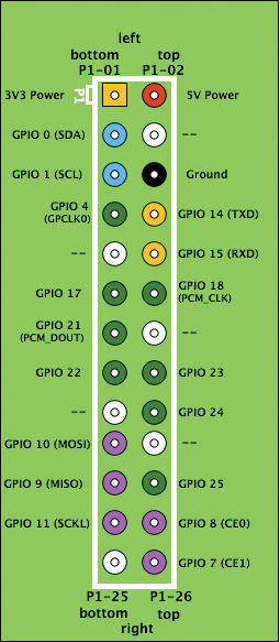
Actually, the SoC has two master interfaces on the I2C bus, whose output is also found in the syslog, but only one of the two is available on the double-row header (P1-03 and P1-05) – the one with the bus-ID 0. You can enable the I2C bus by installing the two drivers i2c-bcm2708 and i2c-dev.
To do this, remove the i2c-bcm2708 driver from the list of drivers that are not to be loaded in /etc/modprobe.d/raspi-blacklist.conf. You specify the i2c-dev driver, which creates the interface in the /dev device directory, in /etc/modules. The bus will be active once the system has been restarted. To activate the bus without rebooting, execute the modprobe i2c-bcm2708 I2C-dev command.
So that you can perform transactions on the I2C bus as a normal user, you will first need to install some corresponding tools and set group permissions:
$ sudo apt-get install i2c-tools
$ sudo addgroup pi i2c
The addresses under which the modules are to be found is revealed by the values found in the output returned by
i2cdetect -y 0
Depending on how you have wired the three address pins of the LM75, the output will contain exactly one value in the hexadecimal range from 0x48 to 0x4f. You then read out the 2-byte temperature word of the LM75 at register address 0 with the command:
$ i2cget -y 0 I2C bus_address register_address w
The data sheet of the module will be of help for converting the cryptic value returned (example: 0x8015) to the corresponding temperature.
Python is a suitable a software environment for the controller, since class libraries already exist for the Raspberry Pi for accessing the I2C bus and the GPIO pins. This example used the quick2wire-python-api and quick2wire-gpio-admin libraries. Listing 7 shows the installation of the packages and libraries.
Listing 7: Python Packages and Libraries
$ sudo apt-get install git python3 python-pip python-virtualenv
$ git clone https://github.com/quick2wire/quick2wire-gpio-admin.git
$ git clone https://github.com/quick2wire/quick2wire-python-api.git
$ cd quick2wire-gpio-admin
$ make
$ sudo make install
$ sudo adduser pi gpio
$ virtualenv TEMPCONTROL
$ source TEMPCONTROL/bin/activate
$ cd quick2wire-python-api
$ sudo python3 setup.py install
The program itself is very simple (Listing 8): It reads the sensor value (line 15) in a cycle of five seconds and converts the sensor reading into the temperature value (line 16). The program then turns the two LEDs on or off accordingly.
Listing 8: Controller Program
01 #!/usr/bin/env python3
02 import quick2wire.i2c as i2c
03 import time
04 from quick2wire.gpio import Pin, exported
05
06 busaddr = 0x48
07 regaddr = 0x00
08 redLED = Pin(16, Pin.Out)
09 greenLED = Pin(18, Pin.Out)
10
11 with exported(Pin(16, Pin.Out)) as redLED, \
12      exported(Pin(18, Pin.Out)) as greenLED, \
13      i2c.I2CMaster() as bus:
14   while True:
15     temp_hib, temp_lob = bus.transaction(i2c.writing_bytes(busaddr, regaddr),i2c.reading(busaddress, 2))[0]
16     temp = (temp_hib << 1 | temp_lob >> 7) / 2.
17     if temp > 25:
18       redLED.value = 1
19       greenLED.value = 0
20     elif temp < 22:
21       redLED.value = 0
22       greenLED.value = 1
23     else:
24       redLED.value = 1
25       greenLED.value = 1
26     print ("%02.01f" % temp)
27     redLED.value = 0
28     greenLED.value = 0
29     time.sleep(5)
The different designations for the GPIO pins are a little confusing. The red and green LEDs are GPIO23/GPIO24, according to the header, but they are also connected to P1-16/P1-18. The first designation corresponds to the BCM2835 documentation and the values from the kernel. However, the Python libraries follow the second nomenclature.
You will need to provide the script with the necessary permissions for execution. After starting, it will continuously output the values measured to the console with each update of the LEDs.
Conclusions
Raspberry Pi is obviously not a desktop system. If using the terminal seems too strange and cryptic to you, you should start with the desktop and work your way to the command line gradually.
From its very conception, the RasPi was conceived as an energy-efficient PC for multimedia applications, and it is clearly intended for use as an embedded system. The hardware is ideally suited for use as a server or process computer, or for controlling tasks in hobby projects that are not too power hungry. The configuration makes it possible to connect necessary peripherals, and the header practically begs you to put together additional features to suit your own needs. A specialized Linux distributions will help make the first steps easier for novices.
The developers have achieved their original goal of making computer technology tangible for interested – and especially young – people. The winter and school year are in their most difficult phases; for the next project in your basement, Raspberry Pi receives our warmest recommendations.
The Author
Werner Hein has been working with Linux as a hobby since 1994 and as a professional with mobile telephony since 1997. His soldering iron had been unused for quite some time until he picked it up again for this article.
Subscribe to our Linux Newsletters
Find Linux and Open Source Jobs
Subscribe to our ADMIN Newsletters
Support Our Work
Linux Magazine content is made possible with support from readers like you. Please consider contributing when you’ve found an article to be beneficial.

News
-
Substantial Update to IPFire Now Available
The lastest version of IPFire features a fundamental change to how the system handles DNS.
-
Gnome Working on Test Center App to Make Testing Easier
It's now possible to test experimental features on the Gnome desktop without worrying that you'll break things.
-
New Vulnerability Discovered in Linux Kernel
Hiding out for nearly 15 years, the Ghostlock vulnerability allows a standard logged-in user to gain root privileges.
-
New Linux Flaw Lets Attackers Escape VMs
A 16-year-old vulnerability allows an attacker to escape a virtual machine, gain access to the host, and execute malicious code.
-
Hannah Montana Linux Is Back!
Developer Noah Cagle decided the world needed the once obscure but beloved Linux distribution and gave it a decidedly pink refresh.
-
System76 Refreshes the Lemur Laptop
If you're looking for a laptop with tons of power and battery, look no further than the latest iteration of the System76 Lemur Pro.
-
More than 43 Million Lines of Code in Linux Kernel 7.2
Using the cloc utility, Michael Larabel of Phoronix discovered that Linux kernel 7.2 has over 43 million lines of code.
-
Kubuntu Focus Goes Ultra
The Kubuntu Focus team has upped the performance ante of its M2 and Zr laptops with the latest, greatest CPUs from Intel.
-
Linux Gamers May Soon See Less Mouse Lag in KDE Plasma
Gamers using KDE’s Plasma desktop have been suffering from a slight input delay in mouse movement that could lead to getting fragged.
-
Three Lines of Code Improve Linux Storage Performance
A developer changed three lines of code, giving Linux storage performance a 5% bump.