Using OpenSCAD to build custom 3D pieces Build Your Own Body

Tutorials – OpenSCAD

Article from Issue 223/2019
Author(s):

OpenSCAD lets you use simple scripts to build 3D bodies from primitive shapes that you can then send to your 3D printer. It also lets you create custom shapes for pieces and objects. In this article, we look at two ways to do just that.

In last month's installment [1], you saw how to use primitive 3D bodies (cubes, spheres, cylinders, etc.) to build complex 3D objects. Apart from combining basic primitives, there are more ways of making bodies in OpenSCAD [2]. One is to extrude them from 2D shapes; another is to build them from a bunch of vertices and faces you define in arrays.

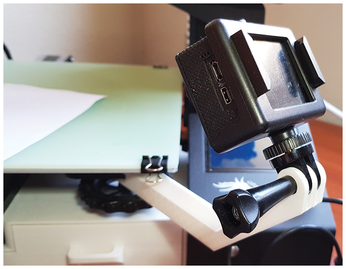
Let's see how both of these work by building an "arm" that will let you attach a sports camera to a printer's hotbed. This arm could look something like what you can see in Figure 1. With the arm attached to the bed, you will be able to monitor your print with the action always in the center of the frame.

Figure 1: An arm for holding a sports camera helps you film your prints.

You will also be able to make cool, if slightly dizzying, time-lapse photographs of the proceedings.

Anatomy of an Arm

By studying my own printer (a Creality 3D Ender 3), I concluded that the best place to affix the arm would be to the hotbed's undercarriage. It doesn't get hot down there, so there is no danger of the plastic getting soft or melting. In addition, by affixing the arm to a corner and threading the screw used for leveling the bed through it, the arm has extra grip and doesn't fall off.

To clear the hotbed and allow the camera to focus properly, the arm would have to be relatively long, at least 10cm. It would also have to bend upwards at some point, so the camera had a good view of what was happening on the bed; otherwise, it would be too low.

Most sports camera accessories have a pretty standard way of connecting one with another. They usually end in two or three semicircular prongs (see Figure 2). You slot a piece with two prongs into a piece with three prongs, and, thanks to the fact that the prongs are curved, you can adjust the angle to your liking. Once adjusted, you use a screw-like bit (Figure 2, bottom right) to tighten the pieces to make sure they don't move.

Figure 2: A typical array of sports camera accessories.

This is how you can connect the arm to the camera, too. You can also use the piece that screws into the bottom of the camera (Figure 3) to attach several other cameras to the arm, since the screw is the standard size used for tripods.

Figure 3: An accessory that allows you to connect nearly any camera to the arm.

To summarize, our arm has a forearm that is 10cm long, plus another section that bends up at a 45-degree angle. At the end, it has a semicircular section. In profile, it would look like Figure 4.

Figure 4: A 2D projection of what your 3D arm will look like.

2D Polygons

Figure 4 shows an OpenSCAD polygon. You create polygons by using the (unsurprisingly) inbuilt polygon() function. In its simplest form, you pass it a list of vertices that are in the order in which you want to draw the polygon itself:

polygon([[0,0], [0,10], [5,15], [10,10], [10,0]]);

The renderer then draws the polygon, in this case, a house-like shape. OpenSCAD will draw from [0,0] to [0,10], then from [0,10] to [5,15], and so on and will finish by closing the polygon, joining [10,0] with the starting point at [0,0].

You can also use the paths() parameter for more complex polygons.

The line

polygon(points=[[5,15], [0,10], [10,10], [0,0], [10,0]], paths=[[3, 1, 0, 2, 4]]);

also draws a house-like polygon, but the points are not in the given order. It is the paths() parameter that tells OpenSCAD in which order to draw the shape.

The usefulness of paths() becomes clear when you need to cut holes in your 2D object.

Consider, for example, Listing 1. You have each object (facade, window, and door) as an array of points (lines 1, 4, and 7). Then you have a path for each object (lines 2, 5, and 8). Concatenate the array of points (line 10) and put the paths into an array of arrays (line 11). Pass everything to polygon() (line 13), and, hey presto, you have yourself a cute little house with a window and a door (Figure 5).

Listing 1

house.scad

01 facade=[[0,0], [0,10], [5,15], [10,10], [10,0]];
02 facade_path=[0, 1, 2, 3, 4];
03
04 window=[[1,6],[1,9],[4,9],[4,6]];
05 window_path=[5, 6, 7, 8];
06
07 door=[[4,0],[4,4],[6,4],[6,0]];
08 door_path= [9, 10, 11, 12];
09
10 house= concat (facade, window, door);
11 house_paths= [facade_path, window_path, door_path];
12
13 polygon(points=house, paths=house_paths);
Figure 5: Using polygon(), points(), and paths(), you can make custom 2D shapes.

Getting back to the arm and the shape shown in Figure 4, the module shown in Listing 2 would do the job of drawing it nicely.

Listing 2

Arm base() Module

01 module base() {
02   polygon([[0,0], [0,100], [50,150], [60,150], [60,135], [50,135], [12,100], [12,0]]);
03   translate([60, 142.5, 0]){
04     circle(d=15, $fn=50, center=true);
05   }
06 }

First you draw all the straight-sided parts of the shape (line 2) and then add a circle at the business end (lines 3 and 4). To get the exact diameter you need, you are going to have to dust off your trusty caliper (Figure 6). A regular ruler is not going to cut it for the precise measurements you need when making pieces that need to fit in with others in the physical world.

Figure 6: A caliper is an essential tool when designing pieces that have to fit in with other physical objects.

Once you have your polygon, the next step is to turn the 2D shape into an actual 3D object. You can do that with the linear_extrude() function.

Here you are again going to need your caliper to measure the object's height. In the case of our arm, placed on its side, it is 15 units (millimeters) high. For an accurate measurement, it is a good idea to center the object, too. This will make it easier to place the shapes you want to subtract from it later.

Listing 3 shows the script for generating the basic body for your arm (Figure 7).

Listing 3

body.scad

01 module body() {
02   linear_extrude(height=15, center = true) {
03     base ();
04   }
05 }
06
07 module base() {
08   polygon([[0,0], [0,100], [50,150], [60,150], [60,135], [50,135], [12,100], [12,0]]);
09   translate([60, 142.5, 0]){
10     circle(d=15,  $fn=50, center=true);
11   }
12 }
Figure 7: A 3D body extruded from a 2D shape.

The final step is to create all the bits and pieces that you have to take away from the arm (Listing 4). You need a slot at one end, so you can fit the arm to your hotbed's undercarriage (lines 2 to 4), and a circular hole through that, so you can thread the leveling screw and spring through it (lines 6 to 10). You will also need two slots at the other end to convert the circular part into three prongs (lines 12 to 18). Again, you will need a hole through all of that, so you can insert the tightening screw and secure it on the other side with a bolt (lines 20 to 23).

Listing 4

slots.scad

01 module slots() {
02   translate([4, -5, -10]) {
03     cube([4,22,20]);
04   }
05
06   translate ([6,7.5,0]) {
07     rotate([0,90,0]) {
08       cylinder(20, d=8.5, center=true, $fn=50);
09     }
10   }
11
12   translate([60,142.5,3]) {
13     cube([20,20,3], center=true);
14   }
15
16   translate([60,142.5,-3]) {
17     cube([20,20,3], center=true);
18   }
19
20   translate([60,142.5,0]){
21     cylinder(20, d=5, center=true, $fn=50);
22   }
23 }

Taking away slots() from body() with the inbuilt difference() function, you get a usable piece like the one shown in Figure 8.

Figure 8: An arm you can print.

For the record, I did print this piece and it worked. However, it was very weak: I could easily snap it without much effort. For a tiny sports camera, it would probably be fine. However, for anything heavier, it would probably break mid-print and drop the camera – not ideal.

Custom Polyhedron

I figured I'd need some reinforcement and looked up online how others solved this problem. One way was to run a triangular beam along the arm and have it connect to the upward curving bit. Apparently, a triangular-shaped beam gives the arm extra resistance.

Each end of the beam would also have to be slanted at a 45-degree angle on one end, so as not to impede the leveling screw and spring, and on the other to meet the bend. The piece looks like Figure 9.

Figure 9: A triangular beam for extra strength.

As this is not a cube, sphere, cylinder, or cone, you can build this piece either by painstakingly rotating and subtracting cubes from one another or by constructing your own polyhedron from scratch.

The second way is easier, and the idea is similar to what you did with the polygon: You define all the polyhedron's vertices (but this time in 3D space instead of on a flat surface), and then you define how they go together in faces.

Listing 5 shows a polyhedron that will draw the beam. Notice that the beam is already drawn in position so that, when rendered along with the rest of the piece, it will appear affixed to the body of the arm in the correct place (Figure 10).

Listing 5

reinforcement.scad

01 module reinforcement() {
02   polyhedron(
03     points= [
04           [12,11.75, -7.5],
05           [18,17.75,0],
06           [12,11.75,7.5],
07           [12,100,-7.5],
08           [18,106,0],
09           [12,100,7.5]
10            ],
11
12     faces=  [
13           [0,2,1],
14           [0,1,4,3],
15           [1,2,5,4],
16           [3,4,5],
17           [0,3,5,2]
18         ]
19   );
20 }
Figure 10: The new arm with its reinforcement in the Cura slicer ready to be printed.

There is one thing you have to take into account when describing your object to the renderer: You can start describing each face with any vertex you want, but you then have to move clockwise after that. And "clockwise" here means "clockwise as if you were facing the object." So, while you would run through the vertices clockwise on a face at the front or on the top of an object, you would have to run through the vertices counterclockwise for faces on the back or bottom of the object.

Say you defined a rectangular face in which the bottom left vertex was  , the bottom right was 1, the top left was 2, and the top right was 3. If it were on the front of your object, you would tell the renderer to draw it with:

[0, 2, 3, 1]

However, if it were on the back of your object, you'd say:

[0, 1, 3, 2]

This may take some mental gymnastics to get right if you are spatially challenged like me. It does help if you draft your body on paper. Either way, if you make a mistake, you will get an error that says WARNING: Object may not be a valid 2-manifold and may need repair!, even if the piece seems to show up correctly in the preview window or even in the slicer.

Buy this article as PDF

Express-Checkout as PDF
Price $2.95
(incl. VAT)

Buy Linux Magazine

SINGLE ISSUES
 
SUBSCRIPTIONS
 
TABLET & SMARTPHONE APPS
Get it on Google Play

US / Canada

Get it on Google Play

UK / Australia

Related content

  • Designing your own stuff with OpenSCAD

    Ah! What a joy your first 3D printer … but once you have printed your first benchy, where do you go from there? To building your own pieces, of course!

  • Mother of Invention

    Designing simple shapes in OpenSCAD is easy, but if you want to print complex machines with multiple interlocking pieces, you need to bring out the big guns. That's where FreeCAD comes in handy.

  • Introduction

    This month in Linux Voice.

  • FOSSPicks

    This month Graham looks at Ardour, FluffyChat, PlugData, Cameractrls, hiSHtory, CadQuery Editor, and more!

  • Tutorials – 3D Printing

    Having covered several ways to design your 3D object, let's cover how we prepare your design for printing.

comments powered by Disqus
Subscribe to our Linux Newsletters
Find Linux and Open Source Jobs
Subscribe to our ADMIN Newsletters

Support Our Work

Linux Magazine content is made possible with support from readers like you. Please consider contributing when you’ve found an article to be beneficial.

Learn More

News