Analog to Digital
Get your Pi to read analog data
ByThe Raspberry Pi still lacks analog GPIOs that would allow it to read directly from temperature and light sensors, or even humble potentiometers. With an inexpensive chip and some homegrown software you can grant the Pi the gift of analog sensing.
Even the most basic Arduino, the UNO, has seven analog pins. In fact, the last time around we tried to make the Pi read analog inputs [1], we used a Digispark – a tiny Arduino compatible board with analog pins. We read from an analog source and passed the digitized data on to the poor old Pi via one of its USB ports.
The solution was inelegant, bordering on messy overkill. It was also much more expensive than it needed to be. We were using an $8 device capable of much more than acting as a mere translator.
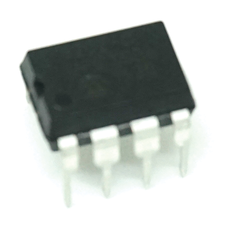
What we really need is an ADC, or an Analog to Digital Converter (Figure 1). These modest little ICs costs about one Euro each, or less if you buy several together.
However, before you start shifting analog data to and fro, you have to learn a little about the SPI protocol.
SPI
The 3202 is a SPI device. SPI [2], or Serial Peripheral Interface, is a cousin of the I2C protocol, that thing Martin Mohr is always droning on about [3]. Similarly to the I2C, SPI is used to send data between microcontrollers and small peripherals, such as shift registers, sensors, SD cards and of course the 320x family of ADCs.
Luckily, the Pi can handle SPI out of the box. To activate SPI on the Raspberry Pi, use the raspi-config tool: go to Advanced > A6 SPI and choose Yes. Alternatively, simply edit /boot/config.txt and remove the # from the line that says
#dtparam=spi=on
to uncomment it.
After making your changes, reboot your Pi to load the SPI drivers into the kernel. Two new devices will appear in /dev: spidev0.0 and spidev0.1.
Use the command gpio readall to see how the pins assigned to the SPI protocol change when the drivers are loaded. In Listing 1, for example, GPIOs 19, 20, 21, 22, 23, 24 and 26 on a Pi 3 change when the SPI system is activated (below) from when deactivated (above).
$ gpio readall # SPI driver not loaded (default)
+-----+-----+--------+------+---+---Pi 3---+---+------+--------+-----+-----+
| BCM | wPi |   Name  | Mode | V | Physical | V | Mode | Name    | wPi | BCM |
+-----+-----+--------+------+---+----++----+---+------+--------+-----+-----+
.
.
.
|     |     |    3.3v |      |   | 17 || 18 | 0 | IN   | GPIO. 5 | 5   | 24  |
|  10 |  12 |    MOSI |   IN | 0 | 19 || 20 |   |      | 0v      |     |     |
|   9 |  13 |    MISO |   IN | 0 | 21 || 22 | 0 | IN   | GPIO. 6 | 6   | 25  |
|  11 |  14 |    SCLK |   IN | 0 | 23 || 24 | 1 | IN   | CE0     | 10  | 8   |
|     |     |      0v |      |   | 25 || 26 | 1 | IN   | CE1     | 11  | 7   |
.
.
.
+-----+-----+--------+------+---+----++----+---+------+--------+-----+-----+
| BCM | wPi |   Name  | Mode | V | Physical | V | Mode | Name    | wPi | BCM |
+-----+-----+--------+------+---+---Pi 3---+---+------+--------+-----+-----+
$ sudo nano /boot/config.txt
$ sudo reboot # See ya later!
$ gpio readall # SPI driver loaded
+-----+-----+--------+------+---+---Pi 3---+---+------+--------+-----+-----+
| BCM | wPi |   Name  | Mode | V | Physical | V | Mode | Name    | wPi | BCM |
+-----+-----+--------+------+---+----++----+---+------+--------+-----+-----+
.
.
.
|  10 |  12 |    MOSI | ALT0 | 0 | 19 || 20 |   |      | 0v      |     |     |
|   9 |  13 |    MISO | ALT0 | 0 | 21 || 22 | 0 | IN   | GPIO. 6 | 6   | 25  |
|  11 |  14 |    SCLK | ALT0 | 0 | 23 || 24 | 1 | OUT  | CE0     | 10  | 8   |
|     |     |      0v |      |   | 25 || 26 | 1 | OUT  | CE1     | 11  | 7   |
.
.
.
+-----+-----+--------+------+---+----++----+---+------+--------+-----+-----+
| BCM | wPi |   Name  | Mode | V | Physical | V | Mode | Name    | wPi | BCM |
+-----+-----+--------+------+---+---Pi 3---+---+------+--------+-----+-----+
If this seems like a lot of changes for one analog input to you, take a look at Figure 2. This will help you understand better how things work. To the left are the MCP3020 pins, the analog to digital converter we have chosen. The Raspberry Pi 3 pins are on the right (this also applies to the Pi 2). These are the pins you're going to use.
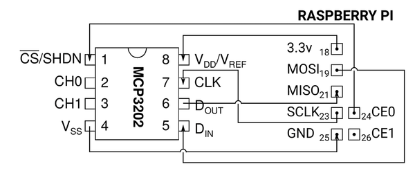
Start by looking at the Pi's pins in order. Starting from the top, pin 18 is a 3.3v output. This will provide power to the 3202, so connect it to its VDD port.
In any SPI relationship, there is a Master device (in this case the Pi) and a Slave device (in this case the MCP3202). The master device issues commands and the slave responds. Pin 19 on the Pi is the MOSI pin, that is, the Master Out/Slave In pin. This is the pin through which you send commands to the slave. It connects to the 3202's Data In (DIN) port.
As you may have guessed, pin 21, aka the MISO pin works in reverse. MISO stands for Master In/Slave Out, and is the pin through which the Pi receives data from the slave. It connects to the 3202's Data Out port.
SPI transactions are synchronous. This means only one transaction can be executed at a time, much like an old fashioned grandfather clock pendulum swings back and forth. In fact, the correct moment for each transaction is dictated by the master device's clock. When the master sends a request for data to the 3202, it counts as one transaction (tick!). When the 3202 answers with the corresponding data, this counts as another transaction (tock!). That's where pin 23 (SCLK) on the Pi comes in. This pin connects to the 3202's CLK (CLocK) port and sets the pace at which transactions will occur.
CE0 (or CE1) connects to the slaves's CS port, also referred to as Chip control, port. It tells your Pi what SPI device it is talking to. By default the SPI driver on the Pi gives you two CEx pins, so your Pi can even talk to two SPI devices simultaneously.
Finally, the 3202's VSS port connects to the Pi's GND on pin 25, closing the circuit.
Note that the 3202 has two ports (2 and 3) labeled CH0 and CH1. You will be connecting your analog sensor to one of them. These are the ports through which the ADC receives the analog data. As you have two, you can connect two sensors to one 3202 chip.
Wiring up
By way of a practical example, let's connect a potentiometer to the 3202 and read in the different values when we turn the knob. You can see a diagram of what the wiring will look like in Figure 3.
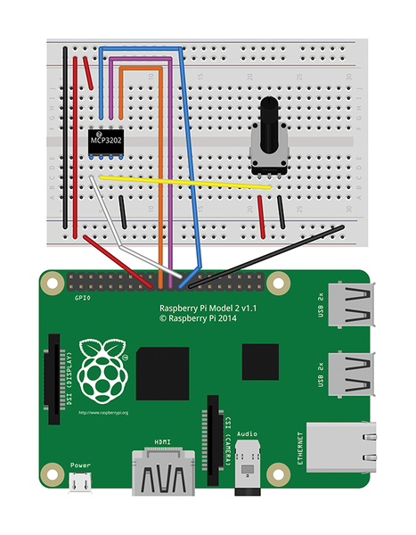
Apart from connecting the Pi to the 3202, you will need to connect the potentiometer's leftmost pin to a power source (the Pi's 3.3v pin will do), and its rightmost pin to GND. The potentiometer's center pin, the one that actually outputs the varying voltage, connects to the 3202's CH0 pin as mentioned above.
Table 1 lists a summary of what connects to what. The first column lists the 3202's pins (see Figure 2), the second columns shows the Pi's pins, and the last column shows the potentiometer's pins.
| 3202 | Raspberry Pi | Potentiometer |
|---|---|---|
| 1 |
24 |
- |
| 2 |
- |
2 |
| 3 |
- |
- |
| 4 |
25 |
3 |
| 5 |
19 |
- |
| 6 |
21 |
- |
| 7 |
23 |
- |
| 8 |
18 |
1 |
Figure 4 shows what the set up may look like in real life if you are as messy at wiring as I am.
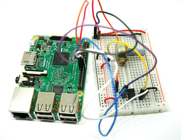
Note to self: acquire shorter jumper cables.
SPI with Python
For the programming part, you'll be using Python. Install the spidev module to proceed:
sudo pip install spidev --upgrade
The --upgrade option is just in case you already have spidev installed, but want to upgrade to the latest stable version anyway.
Thanks to the spidev module, programming for the 3202 is very straightforward. Look at Listing 2 for an example of a boilerplate program that reads from the ADC and prints out the values of the potentiometer to the command line. (All due thanks to Ethan Dicks' work which I have blatantly used as "inspiration" for this program [4].)
01 import spidev
02
03 def bitstring(n):
04    s = bin(n)[2:]
05    return ,0'*(8-len(s)) + s
06
07 def read(spi_channel=0):
08    conn = spidev.SpiDev(0, spi_channel)
09    reply_bytes = conn.xfer2([128, 0])
10    reply_bitstring = ,'.join(bitstring(n) for n in reply_bytes)
11    return int(reply_bitstring, 2)/2047.0
12
13 if __name__ == ,__main__':
14    print read()
Line 1 imports in the spidev module, and lines 13 and 14 make up the main function of the program, obviously.
The read() function (lines 7 to 11) is where things get interesting. On line 8 you create an SpiDev() object [5]. The initialization module takes two parameters: the tells the Pi that this object is going to be associated with SPI device 0, i.e. the device connected to pin 24/CE0. The second parameter tells the device, the 3202, to listen on channel 0, i.e. port 2/CH0 on the 3202. Examine Figures 2 and 3 again if you are getting confused.
The spidev xfer2() function (line 9) carries out a complete transaction between the Pi and the 3202. "Complete", in this context, means it sends out a petition for data in two bytes, and returns the reply. You send it a python list of values containing as many bytes as you want back. The 3202 can deliver 12 bits of information, although bit 12 is always 0 (NULL). As such, you get up to 11 bits of useful data back. This means that means that, once converted, you get a value between 0 and 2047. As a byte is only 8 bits long, you need to send two bytes to the 3202, to get enough bits back.
You can see what the two bytes sent to the 3202 look like by adding the line
print reply_bytes
after line 9. Note the line should start with a tab.
If you run the modified program, you should get something like what is shown in Listing 3.
The first line from the output shows the two bytes (in the shape of a Python list) the 3202 sends back. The second line shows the value converted to one single decimal number.
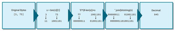
This is, by the way, what you do on line 10: You iterate over the two values in reply_bytes, sending each off to the bitstring() function. bitstring() converts the numbers to a binary string of 0s and 1s and chops of the first two characters (line 4) – Python indicates that a number is binary by preceding it with 0b. It then stuffs the string with 0s to fill the 8 bits that it takes to make up one full byte, then sends it back to read().
Still on line 10, both strings of bits get concatenated together.
On line 11, reply_bitstring, which now contains both bytes concatenated as a binary string, gets converted to decimal, and sent back to the main function for printing. Figure 5 shows the process of converting the two bits into a single decimal number.
Now's the moment to twiddle your potentiometer's knob and marvel at the fact that the Pi can now understand analog inputs.
Analog Epilogue
So what can you do with this? Pong, obviously. The most common version of Pong played on a Raspberry Pi uses a mouse, which is for barbarians. You need a dial to play this classic properly, which is where a potentiometer comes in handy.
Also, by default the Pi can read from two SPI slaves (read "two 3202 ADC devices") at the same time. Each 3202 has two channels, so, theoretically, you could read from four analog sensors at once. This gives you enough to read from a basic temperature sensor, a wind speed sensor, a UV sensor, and a humidity sensor. That's nearly a whole weather station.
Whatever you do, using an ADC opens the Pi to a whole new range of sensing. Enjoy sniffing the analog world!
- Using a Digispark for analog input: http://www.raspberry-pi-geek.com/Archive/2014/03/Adding-analog-input-to-the-Pi-using-the-Digispark/
- Serial Peripheral Interface: https://en.wikipedia.org/wiki/Serial_Peripheral_Interface_Bus
- Martin Mohr on the I2C: http://www.raspberry-pi-geek.com/Archive/2015/09/Getting-to-know-the-Raspberry-Pi-I2C-bus
- Ethan Dicks adds an ADC to his Pi: https://ethandicks.wordpress.com/2013/06/19/adding-analog-input-to-raspberry-pi/
- Full list of spidev's modules and attributes: http://tightdev.net/SpiDev_Doc.pdf
next page » 1 2
Subscribe to our Linux Newsletters
Find Linux and Open Source Jobs
Subscribe to our ADMIN Newsletters
Support Our Work
Linux Magazine content is made possible with support from readers like you. Please consider contributing when you’ve found an article to be beneficial.

News
-
Hannah Montana Linux Is Back!
Developer Noah Cagle decided the world needed the once obscure but beloved Linux distribution and gave it a decidedly pink refresh.
-
System76 Refreshes the Lemur Laptop
If you're looking for a laptop with tons of power and battery, look no further than the latest iteration of the System76 Lemur Pro.
-
More than 43 Million Lines of Code in Linux Kernel 7.2
Using the cloc utility, Michael Larabel of Phoronix discovered that Linux kernel 7.2 has over 43 million lines of code.
-
Kubuntu Focus Goes Ultra
The Kubuntu Focus team has upped the performance ante of its M2 and Zr laptops with the latest, greatest CPUs from Intel.
-
Linux Gamers May Soon See Less Mouse Lag in KDE Plasma
Gamers using KDE’s Plasma desktop have been suffering from a slight input delay in mouse movement that could lead to getting fragged.
-
Three Lines of Code Improve Linux Storage Performance
A developer changed three lines of code, giving Linux storage performance a 5% bump.
-
AUR Hit Again with Malicious Packages
Once again the Arch User Repository is plagued by a high volume of malicious packages.
-
Alpine Linux 3.24 Features Fresh Desktops and a Newer Kernel
If you're a fan of Alpine Linux, it's time to upgrade because the latest version has been released with KDE Plasma 6.6, Gnome 50, and Linux kernel 6.18 LTS.
-
EU Open Source Strategy Plays Key Role in Tech Sovereignty Package
Comprehensive measures adopted by the European Commission aim to reduce dependency on non-EU countries.
-
Linux Foundation Report Indicates AI Driving Tech Hiring
Within growing security and skills gaps, AI has been found to be a positive driving force behind tech hiring trends in Europe.